Computer-Generated Holography (CGH)
PHYS4412 (Computational Science II)
Department of Physics & Astronomy
Louisiana State University
![]()
PHYS4412 (Computational Science II)
Department of Physics & Astronomy
Louisiana State University
![]()
| II.A | One-Dimensional Aperture, Tilted with Respect to the Image Screen |
|---|
In Chapter I, we considered only apertures that were oriented parallel to the image screen. This is appropriate for determining the holographic image of an object in only very limited situations; for example, it applies to the red cube shown in in Figure I.2, but only because the cube is oriented such that one of its faces is parallel to the image screen. For practically any other orientation, three separate faces of the cube will be visible from every point on the image screen and, although they each can be described as a flat, square aperture, each of the apertures will be inclined to the screen. Hence, we must learn how to evaluate the amplitude and phase of light which hits the image screen from an aperture that is inclined to the screen.
General Concept
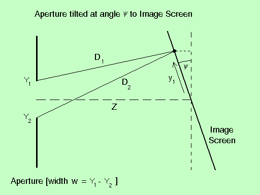
Consider the complex amplitude of light A(y1) that is incident at a location y1 along an image screen whose center is located a distance Z from a slit of width w, but that is tilted at an angle y with respect to the aperture, as illustrated in Figure II.2.
| Figure II.2 |
|
[It might seem more natural to continue to draw the image screen vertically and then to tilt the aperture with respect to the screen's coordinate system, as has been done by Leseberg & Frère (1988) and Patorski (1983). But as we shall demonstrate, it actually proves to be much easier to understand and to generalize our derived results if they are cast first in terms of a coordinate system that is tied in a natural way to the aperture, as shown here.]
If we again consider the case where the phase f = 0 at all locations along the slit, the expression for A(y1) is given by equation (6) from Chapter I.A , namely,
| A (y1) | = | S aj exp[ i ( 2p Dj/ l ) ] |
where, as before, the summation is taken over all "j" elements of light along the aperture, but now,
| Dj | = | [ ( Yj - y1 cosy )2 + ( Z - y1 siny )2 ]1/2 |
| = | L [ 1 - ( 2 y1 cosy Yj )/L2 + Yj2/L2 ]1/2 |
| L | ş | [ ( Z - y1 siny )2 + ( y1 cosy )2 ]1/2 |
| = | [ Z2 + y12 - 2 Z y1 siny ]1/2 . |
If | Yj / L | << 1, we can drop the quadratic term in favor of the linear one in expression (2) and deduce that,
| Dj | » | L [ 1 - ( y1 cosy Yj ) / L2 ] . |
Hence, equation (1) becomes,
| A (y1) | » | A0 S aj exp{ - i [ 2p ( y1 cosy Yj ) / ( lL ) ] } , |
where, as before, A0 = exp[i(2p L / l ) ].
Analytical Result
If, as in Chapter I.A, we consider the limit where the aperture shown in Figure 2 is divided into an infinite number of divisions, then we can convert the summation in equation (5) into an integral running between the limits, Y2 and Y1. Specifically, equation (5) becomes,
| A (y1) | » | A0 a0 | ň | exp{ - i [ 2p ( y1 cosy Y ) / ( lL ) ] } dY . |
Following the same sequence of steps as in Chapter I.A, this integral can be completed analytically to give,
| A (y1) | » | A0 a0 w e( - i J1 ) sinc( b1 ) , | |
where, here,
| b1 | ş | p y1 cosy ( l L )-1 [ Y1 - Y2 ] = p y1 cosy w ( l L )-1 , |
| J1 | ş | p y1 cosy ( l L )-1 [ Y1 + Y2 ] . |
Hence, the form of the solution for A is identical to its counterpart in the case when the slit is oriented parallel to the image screen, but the actual result is different because, the angle y enters into the calculation of b1, J1, and L.
Discussion
Before we head into a discussion of tilted, two-dimensional apertures, it is worth noting that the result presented here in the form of equations (7) and (8) could have been derived by inspection from equations (I.A-13) and (I.A-12), respectively, had we been clever enough to appreciate what was actually being derived. Although we have presented the derivations in this chapter as well as in Chapter I.A in the context of wanting to know the complex amplitude of light that falls across an entire (geometrically flat) image screen, in reality what we have done, first, is derive the complex amplitude of light that has collected at one particular point in space and then realized that the analytical result also works for arbitrary locations along the (flat) screen.
If, for the moment, we focus back on the single point, we see that in both chapters the quantity "L" that enters into the calculation of b1 and J1 is simply the distance measured from the origin of the aperture to the point in question which, in terms of the Cartesian coordinate system (xa, ya, za) that is affixed to the aperture is,
| L = [ za2 + ya2 ]1/2. |
Furthermore, in both cases, the angles b1 and J1 are obtained by multiplying a particular wave number (respectively, kb and, kJ ) by the point's "vertical" location ya, as measured in the aperture coordinate system. That is to say,
| b1 | = | kb ya, |
| J1 | = | kJ ya, |
where,
| kb | ş | p ( l L )-1 [ Y1 - Y2 ] , |
| kJ | ş | p ( l L )-1 [ Y1 + Y2 ] . |
So, the results of Chapter I.A can be obtained from equations (7), and (9)-(11), above, by realizing that when the image screen is aligned parallel to the aperture (as shown in Figure I.1), ya = y1 and za = Z. And the results of this chapter can be obtained from the same set of equations by realizing that when the image screen is tilted with respect to the aperture (as shown in Figure II.2), ya = y1cosy and za = Z - y1siny. With this understanding, it should now be possible to immediately calculate the complex amplitude A at any group of points in space, relative to the aperture -- even along an arbitrarily curved image screen.