Computer-Generated Holography (CGH)
PHYS4412 (Computational Science II)
Department of Physics & Astronomy
Louisiana State University
PHYS4412 (Computational Science II)
Department of Physics & Astronomy
Louisiana State University
| I.C | Relevance to Holograms |
|---|
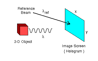
Okay, so what do Chapters I.A and I.B have to do with the numerical construction of a hologram? Well, this is best explained by borrowing an illustration from the Nishikawa et al. (1997) paper (redrawn here as Figure I.2), and comparing it to Figure I.1 from Chapter I.A.
| Figure I.2 |

|
In general, a hologram is made by combining light of wavelength l that is coming from the surface of a 3-dimensional object with coherent light from a reference beam of wavelength lref . The interference pattern that is created on the "image screen" via the combination of these two separate sources of light is recorded (usually in the form of an exposed piece of photographic film) as the hologram. Let's consider the behavior of these two sources of light, separately.
Light from the Object
The discussions in Chapters I.A and I.B illustrate how light that originates from an extended object (aperture) illuminates various points along the image screen. For example, from the perspective of the image screen, the front vertical edge of the red cube shown above in Figure I.2 looks like a vertical, one-dimensional "slit" aperture of width "w", as illustrated in Figure I.1. Hence, the complex amplitude of light that is striking various points "y" along any vertical column of the image screen (hologram) due solely to the light coming from this edge of the cube is given by expression (I.A-13), that is,
| A ( y ) | » | A0 a0 w sinc ( b ) , | |
| b | = | p y w ( l L )-1 , |
| L | = | [ Z2 + y2 ]1/2 , |
Z is the shortest distance measured between the front vertical edge of the cube and the selected column of the image screen, and for purposes of illustration, we have set to zero the offset phase angle J1 that appears in equation (I.A-13).
However, as depicted in Figure I.2, the image screen is not being illuminated by just one vertical edge of the cube but, instead, by one entire two-dimensional face of the cube (the side of the cube that is facing to the right and is therefore not visible in the figure). From the perspective of the image screen (hologram), the surface of the cube looks like a two-dimensional aperture of width "w" and height "w." Therefore, the more complete expression for the complex amplitude of light striking the image screen is,
| A ( x, y ) | » | A0 a0 w2 sinc ( a ) sinc ( b ) , | |
| a | = | p x w ( l L )-1 , |
| b | = | p y w ( l L )-1 , |
| L | = | [ Z2 + x2 + y2 ]1/2 , |
as given by equations (I.B-7) and (I.B-8). (Note that, again for the sake of illustration, we have set the two offset phase angles Q1 = J1 = 0.)
Light from the Reference Beam
The complex number R representing the light amplitude and phase of the reference beam at any position ( x, y) on the image screen is, simply,
| R( x, y) = aref exp{ -i fref } . |
It is customary to consider the reference beam to be a laser that is capable of producing a coherent plane wave which is broad enough in extent to easily illuminate the entire image screen. Then, if the propagation vector kref of the reference plane wave is tilted about the y-axis of the image screen at an angle zref with respect to the unit vector nscreen that is normal to the image screen,
| fref = 2p x sin( zref ) / lref . |
Combined Light Sources
Combining these two sources of light, the complex amplitude of light hitting the image screen (hologram) will be,
| W( x, y) = A( x, y) + R( x, y) , |
or, since the intensity of the light I(x,y) that gets recorded on the film (hologram) is actually the magnitude of this complex amplitude, we have,
| I( x, y) | = | W W* |
| = | A A* + R R* + 2 ( ARe RRe + AIm RIm ) . |
As Trestor (1996) and Nishikawa et al. (1997) both clearly explain, it is the last terms on the right-hand-side of equation (8) involving cross-products of A and R that play the most important role in holography. When the intensity of light produced by these terms is properly recorded on a piece of transparent film, a virtual image of the original object can be retrieved by shining the original reference beam back through the film at the proper angle zref relative to the surface of the film. We shall say more about this important issue in Chapter I.D.