Computer-Generated Holography (CGH)
PHYS4412 (Computational Science II)
Department of Physics & Astronomy
Louisiana State University
PHYS4412 (Computational Science II)
Department of Physics & Astronomy
Louisiana State University
| II.C | Rectangular Aperture with an Arbitrary (Euler Angle) Orientation |
|---|---|
| with Respect to the Hologram |
Here we wish to consider the situation where the rectangular aperture (2D surface of a solid rectangle) has an arbitrary orientation with respect to the image screen (hologram), and derive the transformation equations relating the (xh,yh) coordinates of any point on the surface of the hologram to the Cartesian coordinate system (xa,ya,za) that is affixed to the aperture. Once the three functional expressions xa(xh,yh), ya(xh,yh), and za(xh,yh) have been derived, the expressions presented at the end of § II.B, namely,
| A (xa,ya,za) | » | A0 a0 (w h) e[ - i (Q1 + J1 ) ] sinc( a1 ) sinc( b1 ) , | ||
| a1 | = | ka xa, |
| Q1 | = | kQ xa, |
| b1 | = | kb ya, |
| J1 | = | kJ ya, |
| ka | º | p ( l L )-1 [ X1 - X2 ] , |
| kQ | º | p ( l L )-1 [ X1 + X2 ] , |
| kb | º | p ( l L )-1 [ Y1 - Y2 ] , |
| kJ | º | p ( l L )-1 [ Y1 + Y2 ] , |
| L = [ za2 + ya2 + xa2 ]1/2. |
can be immediately used to determine the complex amplitude of light at all positions on the hologram that will result from one rectangular aperture.
General Coordinate Transformations
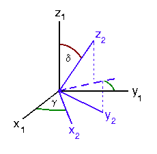
It is customary to define the relative orientation of two Cartesian coordinate systems in terms of two Euler angles (g,d), as illustrated here in Figure II.2. Note that the Euler angles are introduced such that the 2nd (i.e., blue) coordinate system is "twisted" by an angle g about the z1-axis, first, then the 2nd coordinate system is tipped by an angle d about the x2-axis. Hence, the x2 axis lies in the x1-y1 plane and defines the line of intersection between the x1-y1 and x2-y2 planes.
| Figure II.2 |
|---|
 |
Then, quite generally, the following relationships hold:
| Transformation Equations | |
|---|---|
| 2 --> 1 | 1 --> 2 |
| x1 = x2 cosg - ( y2 cosd + z2 sind ) sing | x2 = x1 cosg + y1 sing |
| y1 = x2 sing + ( y2 cosd + z2 sind ) cosg | y2 = ( y1 cosg - x1 sing ) cosd - z1 sind |
| z1 = z2 cosd - y2 sind z2 cosd | z2 = ( y1 cosg - x1 sing ) sind + z1 cosd |
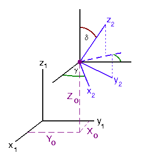
We will also want to consider situations in which the origins of the two coordinate systems do not coincide, but are offset as illustrated in Figure II.3 by the coordinates (X0,Y0,Z0) as measured in the 1st coordinate system.
| Figure II.3 |
|---|
 |
Then the expressions that transform from one system of Cartesian coordinates to the other become,
| Transformation Equations | |||||
|---|---|---|---|---|---|
| 2 --> 1 | 1 --> 2 | ||||
| x1 = X0 + x2 cosg - ( y2 cosd + z2 sind ) sing | x2 = ( x1 - X0 ) cosg + ( y1 - Y0 ) sing | ||||
| y1 = Y0 + x2 sing + ( y2 cosd + z2 sind ) cosg |
|
||||
| z1 = Z0 + z2 cosd - y2 sind |
|
||||
Specific Cases
| X0 = Y0 = 0 and g = 0 |
|---|
In §§ II.A and II.B (see especially Figure II.2), we examined the situation where, in the notation of Figure II.3, the 1st coordinate system was affixed to the aperture, the 2nd coordinate system was affixed to the image screen (hologram), and the orientation of the rectangular aperture relative to the screen was such that,
| g | = | 0 , |
| d | = | y , |
| X0 | = | 0 , |
| Y0 | = | 0 , |
| Z0 | = | Z . |
By the transformation equations given above, we therefore deduce that every point across the plane of the hologram (for which, by definition, zh = 0), has a position in the reference frame of the aperture given by the coordinates,
| xa | = | X0 + xh cosg - ( yh cosy + zh siny ) sing |
| = | xh , | |
| ya | = | Y0 + xh sing + ( yh cosy + zh siny ) cosg |
| = | yh cosy , | |
| za | = | Z0 + zh cosy - yh siny |
| = | Z - yh siny . |
This is in complete agreement with the coordinate expressions given in the sentence following equation (21) of § II.B.
| X0 = Y0 = 0 |
|---|
| xa | = | xh cosg - yh cosy sing , |
| ya | = | xh sing + yh cosy cosg , |
| za | = | Z0 - yh siny . |
When plugged into equations (1) and (2), above, these coordinates provide the generalized expression for A that was alluded to by Patorski (1983) and should produce an "image screen" pattern that closely matches his experimentally produced image in the last figure of his article.