Computer-Generated Holography (CGH)
PHYS4412 (Computational Science II)
Department of Physics & Astronomy
Louisiana State University
![]()
PHYS4412 (Computational Science II)
Department of Physics & Astronomy
Louisiana State University
![]()
| III.B | Understanding How Object Surfaces are Specified in VRML Files |
|---|
In order to define the surface of a three-dimensional object using VRML techniques, one must first define the surface in terms of a "wireframe" model. A wireframe model is constructed by first specifying the coordinates of various strategically placed points (vertices) that lie on the surface of the object, then specifying how subsets of these points are to be connected in sequence in order to form various polygons that coincide with individual (flat) segments of the surface.
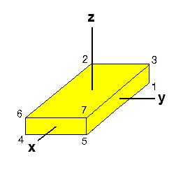
Example #1: A Rectangular Parallelepiped
One of the simplest examples is the wireframe model of a rectangular parallelepiped of width 2w, height 2h, and depth 2d, as depicted here in Figure III.4.
| Figure III.4 | |||||||||||||||||||||||||||||||||||||
|---|---|---|---|---|---|---|---|---|---|---|---|---|---|---|---|---|---|---|---|---|---|---|---|---|---|---|---|---|---|---|---|---|---|---|---|---|---|
|
|
||||||||||||||||||||||||||||||||||||
The entire surface of the rectangular parallelepiped shown in Figure III.4 can be completely specified by eight vertices (numbered 0 through 7 in the figure; but note that the vertex numbered zero is hidden from view) and six four-sided (rectangular) polygons. If we locate the origin of the object coordinate system at the geometric center of the rectangular parallelepiped and orient it such that the principal axes of the object coordinate system pass through the center of each of the six faces of the object (as depicted in Figure III.4), then the eight vertices will have the coordinate locations identified by the tabulated values in Figure III.4.
At the bottom of this page we have attached the ASCII text of a "wrl" (VRML) file that properly constructs a rectangular parallelepiped very similar to the one shown here (but of a different color). Notice that this file contains the following twelve lines of text:
   coord Coordinate {
      point [
      -5.0 -2.0 -0.75,
      -5.0  2.0 -0.75,
      -5.0 -2.0  0.75,
      -5.0  2.0  0.75,
       5.0 -2.0 -0.75,
       5.0  2.0 -0.75,
       5.0 -2.0  0.75,
       5.0  2.0  0.75,
      ]
   }
Each of the eight lines of numbers that lies between the "point"
brackets specifies the
(xobj,yobj,zobj)
coordinates in the object coordinate system of one of the eight
vertices. By design in any wrl file, the first set of coordinates is
assigned to
vertex number 0; the second set of coordinates is assigned to vertex number
1; and, in general, the nth set of coordinates is assigned
to vertex number (n - 1). By comparing the vertex (i.e., point)
coordinates in this specific wrl file with the table of vertex
coordinates shown in Figure III.4, it is clear that the VRML object
that will be drawn from this wrl file will have a half-width w = 5.0,
a half-depth d = 2.0, and a half-height h = 0.75.
|
In constructing a wrl file, you need not list the vertices (points) in any particular order. For purposes of clarity only, the order in which they appear in the wrl file printed below has been designed to correspond with the vertex numbering shown in Figure III.4. But once the vertices have been specified in a particular order, that ordering becomes important as you move to the next step, which involves specifying which vertices will be connected in sequence in order to define each surface polygon. |
The wrl file at the bottom of this page also contains the following eight lines of text:
   coordIndex [
      0, 2, 3, 1, -1,
      0, 1, 5, 4, -1,
      5, 1, 3, 7, -1,
      5, 7, 6, 4, -1,
      6, 2, 0, 4, -1,
      2, 6, 7, 3, -1,
   ]
Each of the six lines of integers that lies between the "coordIndex"
brackets (and is delimited by the integer "-1") specifies
which vertices (as numbered in Figure III.4) are to be connected --
and in what order they are to be connected -- in order to construct
one of the six faces of the rectangular parallelepiped. For example,
the 5th line which reads,
5, 7, 6, 4, -1,
instructs your VRML viewer to connect the vertices numbered
5, 7, 6, 4, then back to 5, in a counterclockwise sequence
in order to form the front face of the
rectangular parallelepiped as illustrated here in Figure III.4.
(Note that if you list the same set of vertices but specify that
they be connected in a clockwise sequence, your VRML browser
will probably make that face of the rectangular parallelepiped
transparent and, therefore, it will be invisible.)
Example #2: What is This Object?
In order to test whether or not you understand how to interpret the coordinate date in a VRML file, examine the following lines of text which specify the vertices and polygons of a familiar geometric solid that is not a rectangular parallelepiped.
   coord Coordinate {
      point [
   -3.0  3.0 -4.0,
    3.0  3.0 -4.0,
    0.0 -3.0 -4.0,
    0.0  0.0  4.0,
      ]
   }
   coordIndex [
     0, 1, 2, -1,
     0, 3, 1, -1,
     1, 3, 2, -1,
     2, 3, 0, -1,
   ]
Now click here in order to download
this "mystery" object into your VRML viewer to see whether or not your
interpretation is correct.
| RECTANGULAR PARALLELEPIPED |
| The ASCII text that follows forms a complete "wrl" (VRML) file that constructs a rectangular parallelepiped very similar to the one shown above in Figure III.4, although of a different color. If you would like to download this wrl file into your browser to see the rectangular parallelepiped in three dimensions click here. But please DON'T DOWNLOAD this "wrl" file unless you are sure you have a working VRML plug-in for your computer. |
#VRML V2.0 utf8
#Created using createVRML.c

Background {
	skyColor 0.58824 0.24706 0.63922 # purple
}

Transform {
	translation 0 0 0
	rotation 0 0 0 0
	scale 1 1 1
	children DEF Default Viewpoint {
		position 0 0 40
		orientation 0 0 1 0
	}
}

DEF URAMask Transform {
	translation 0 0 0
	rotation 1 0 0 -1.57
	scale 1 1 1
	children [
		Shape {
			appearance Appearance {
				material Material { }
			}
			geometry IndexedFaceSet {
				creaseAngle 6.283
   coord Coordinate {
      point [
      -5.0 -2.0 -0.75,
      -5.0  2.0 -0.75,
      -5.0 -2.0  0.75,
      -5.0  2.0  0.75,
       5.0 -2.0 -0.75,
       5.0  2.0 -0.75,
       5.0 -2.0  0.75,
       5.0  2.0  0.75,
      ]
   }
   coordIndex [
      0, 2, 3, 1, -1,
      0, 1, 5, 4, -1,
      5, 1, 3, 7, -1,
      5, 7, 6, 4, -1,
      6, 2, 0, 4, -1,
      2, 6, 7, 3, -1,
   ]
				color Color {
					color [
		0.087157 0 0.996195,
		0.2841872 0.3225579 0.996195,
		0.0789911 0.0368341 0.996195,
		0.0713949 0.0499912 0.996195,
		0.087157 4.62558e-07 0.996195,
		0. 0. 1.0,
		0. 0.5 1.0,
					]
				}
				colorPerVertex TRUE
			}
		}
	]
}